The FIA is completely rewriting the new front wing rules for the 2019 F1 season as a consequence of Haas’s disqualification from September’s Italian Grand Prix, RaceFans understands.
At a meeting of the FIA Technical Working Group on Monday teams unanimously agreed the new rules, which will increase front wing widths to two metres, should be revised to eliminate possible areas for confusion.
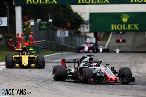
The move came about after Romain Grosjean’s Haas VF-18 was disqualified from sixth place at Monza. The stewards found the car’s floor failed to comply with the technical regulations because its front corners did not have radii of 50mm (to within a permitted tolerance of 2mm).
This has prompted teams to call for next year’s front wing rules to be rewritten to eliminate any potential grey areas. At the meeting, held at the Heathrow Sofitel, the FIA’s head of single-seater matters Nikolas Tombazis undertook to rewrite the new-for-2019 regulations.
The teams are understood to have requested more specific details of the dimensions and specifications of the wings. They also pushed for the elimination of vague language referring to terms such as “minimal” deviations to remove grey areas from the rules.
Grosjean was stripped of sixth placeAs well as making the front wings wider, the new rules are intended to eliminate the ‘outwashing’ effect of the current front wings. This is believed to be partly responsible for why Formula 1 cars cannot follow each other closely at speed.
In May, after the planned rules changes was announced, Tombazis admitted there was a “degree of risk” that any rules change could have unintended consequences or offer teams loopholes they could exploit. “These are no exception in that regard,” he said.
“We cannot ever be completely certain of every single thing teams will do in development. What we’ve tried to do with these rules is to have much more careful wording on some areas of the car to try to avoid any particular loopholes or completely different directions teams could take.”
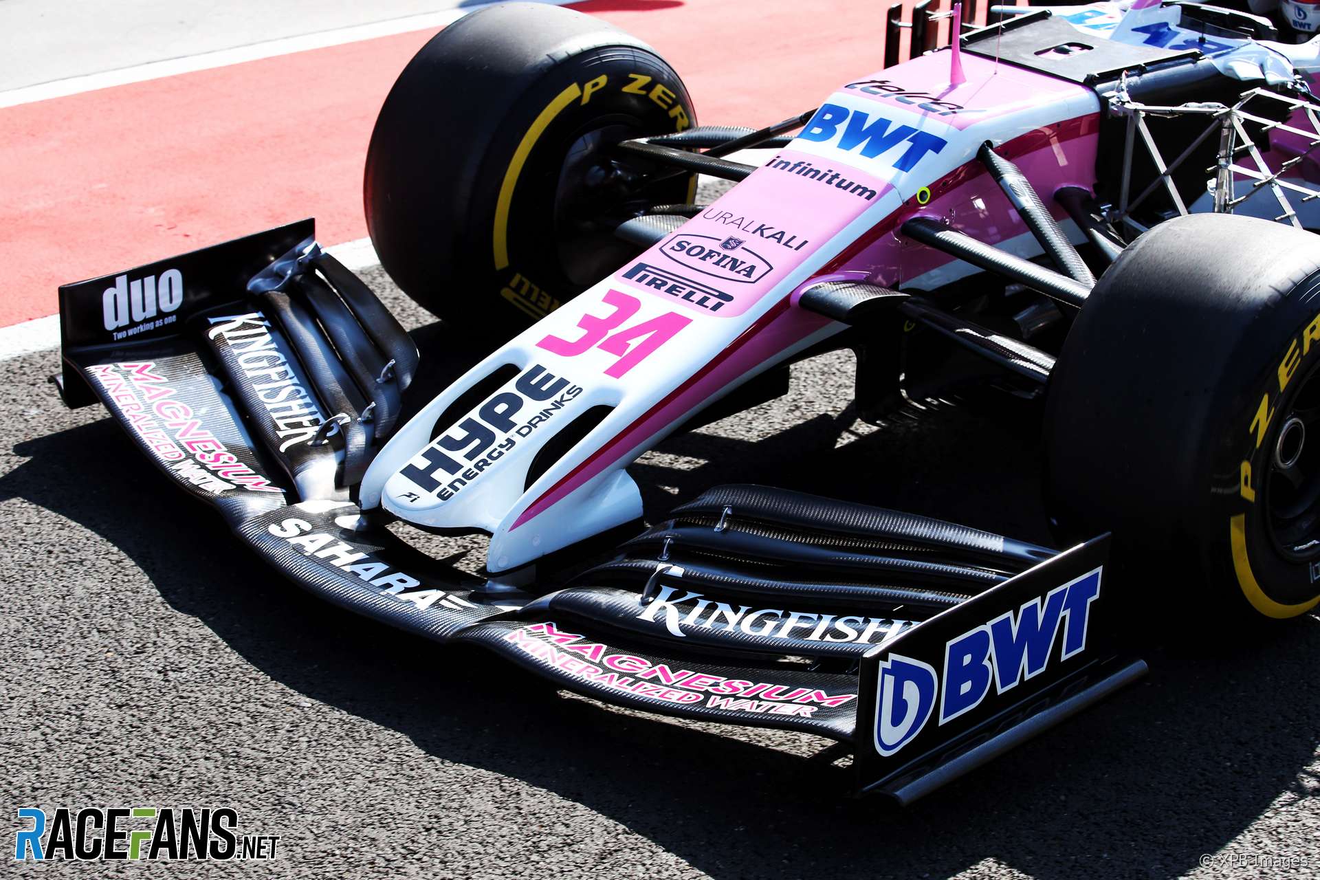
The following is the 2019 front wing regulations as they were originally published. These are now being revised:
3.3.4 Definition of components On each side of the car, the volume described in Article 3.3.3 can only contain the following components:
a) The front wing endplates defined in Article 3.3.5. b) The front wing profiles defined in Article 3.3.6. c) A maximum of two front wing strakes as defined in Article 3.3.8. d) The front wing auxiliary components defined in Article 3.3.9.
3.3.5 Front wing endplates
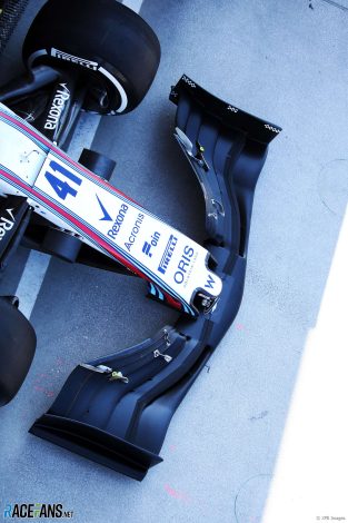
Williams tested a 2019-style front wingA mathematical surface (referred to as the “virtual endplate surface”) must be constructed in order to subsequently define the endplate. The virtual endplate surface must: a) Lie entirely between 910mm and 950mm from the car centre plane. b) Extend forwards, rearwards, upwards and downwards in such way as to intersect respectively the forward, rearward, upper and lower bounding surfaces of the volume defined in Article 3.3.3 over its entire length and height. c) In no place have a normal which subtends an angle greater than 15° to an axis normal to the car centre plane. d) Produce one single continuous curve, which is entirely visible from side view, when intersected with any lateral or horizontal plane.
The front wing endplate is defined as the bodywork created by the union of two volumes.
The first such volume: e) Must fully enclose a minimum of 95% of the virtual endplate surface. f) Over its forward-most 150mm, measured in the longitudinal direction, must in no part be distant more than 10mm from the virtual endplate surface, while over the rest of its volume must in no part be more than 6mm distant from the virtual endplate surface. g) Is a single volume which contains no apertures and any intersection with any lateral or horizontal plane may only produce a single closed section.
The second such volume: h) Must have no part which is distant more than 30mm from the virtual endplate surface towards the car centre plane. Any part inboard of the virtual endplate surface must lie in its entirety between 75mm and 85mm above the reference plane. i) Lies in its entirety between 75mm and 110mm from the reference plane. j) Is a single volume which contains no apertures or slots. k) When viewed from below, has a boundary which does not contain any external local concave radius of curvature smaller than 200mm.
Once the two volumes have been defined, a fillet radius of up to 5mm will be permitted where they intersect. Any cross section of the unified volume with a lateral vertical plane should contain only a single closed section.
In order to prevent tyre damage to other cars, the complete endplate, with the exception of parts of the second volume inboard of the virtual endplate surface must be at least 10mm thick (being the minimum distance when measured normal to the surface in any direction) with a 5mm radius applied to all extremities.
In addition, the leading 50mm of this bodywork must be of a prescribed laminate, details of this laminate may be found in the Appendix to the Technical Regulations.
3.3.6 Front wing profiles
Front wing profiles are defined as bodywork that is contained in the volume which extends from 250mm to 950mm from the car centre plane, and within the volume defined in Article 3.3.3. They must meet the following criteria: a) Any intersection of these profiles with any longitudinal vertical plane may contain no more than five closed sections, each of which may contain no concave radius of curvature less than 50mm. The rearmost closed section may have a ‘gurney’ type trim tab fitted to its trailing edge provided no dimension of it exceeds 10mm. b) For the part of the profiles outboard of a plane that lies 400mm from the car centre plane: i) The rearmost point of every closed section must be visible when viewed from below. ii) With the exception of the rearmost closed section, the rearmost point of every closed section must not be visible when viewed from above. iii) The normal to any point of the profiles’ surface must not subtend an angle greater than 15° to a vertical plane which is normal to the diagonal line described in Article 3.3.3(a). c) Outboard of a plane that lies 400mm from the car centre plane the minimum distance between adjacent sections at any longitudinal vertical plane must lie between 5mm and 15mm at their closest position. Minimal exceptions to the above geometrical criteria can occur in areas of transition close to consecutive longitudinal vertical cross sections with a different number of individual profiles. Outboard of a longitudinal plane that lies more than 400mm from the car centre plane, such changes may only be achieved by the bifurcation of a single closed section into two or more closed sections, and the method of construction of this transition is detailed below. The area of transition will be defined by two vertical planes, which are parallel to each other, up to 20mm apart, and form an angle of no more than 20° to the car centre plane. Within this area: d) The inboard (single) profile surface must be defined over the full span of the transition area in full compliance with Article 3.3.6. e) The outboard profile (two or more) surfaces must be defined over the full span of the transition area in full compliance with Article 3.3.6, lie entirely within the single profile surface, and share the same overall chord. f) Once the inboard and outboard profile surfaces have been defined, blending surfaces must be defined to join the profiles together. These surfaces must lie within the volume of the single, inboard profile surface, and entirely within the transition volume. Once these minimal transition surfaces have been defined, the original overlapping surfaces of the inboard and outboard profiles must be trimmed accordingly. Once the front wing profiles have been defined, they must be trimmed by the virtual endplate surface defined in Article 3.3.5, and the portion of the front wing profiles outboard of that surface must be discarded. Where the front wing profiles intersect the front wing endplate, a maximum fillet radius of 10mm may be applied.
3.3.7 Adjustability of front wing
Once the Front Wing Profiles have been defined in accordance with Article 3.3.6, a portion of up to four of the rearmost profiles may be adjustable in order to trim the front wing aerodynamic load. For this purpose: a) The parts of the front wing profiles that are included within the adjustable part must have no degrees of freedom between them. b) The adjustment may only be a rotation about a fixed axis. The original position of these profiles (as defined in accordance with Article 3.3.6) must be included within the overall range of adjustment. Furthermore, the maximum deviation for any point of these profiles between the uppermost and lowermost angle of adjustment must not exceed 35mm. Minimal exceptions to the geometrical criteria for the wing profiles may be made in the junction between the adjustable and non-adjustable parts, in order to ensure the necessary level of sealing. For the avoidance of doubt, the adjustment permitted under this Article is only allowed when the car is stationary and by the use of a tool, and in accordance with the Formula 1 Sporting Regulations. Furthermore, any such variation of incidence maintains compliance with all of the bodywork regulations, with the exception of Articles 3.3.6 (a) and 3.3.6 (b).
3.3.8 Front wing strakes
Strakes may be constructed once the front wing profiles have been defined. For each strake, a virtual strake surface must be first defined, which must: a) Be connected to the non-adjustable part of the front wing profiles. b) Lie in its entirety between two vertical longitudinal planes, 20mm apart, and between 500mm and 800mm from the car centre plane. c) Lie entirely between 75mm and 150mm from the reference plane. d) Not be closer than 50mm in any point to the other such virtual strake surface. e) In no place have a normal which subtends an angle greater than 10° to an axis normal to the car centre plane. f) Contain no more than one curve when intersected by any lateral vertical or horizontal plane. In side view, no part of the virtual strake surface may obstruct any other part of it.
Once the virtual strake surface has been defined, the strake itself must: g) Fully enclose the entire virtual strake surface. h) In no part lie vertically above the upper surface of the front wing profiles defined in Article 3.3.6. i) Be no more than 6mm distant from the virtual strake surface, except its rear-most 100mm (measured in the longitudinal direction), where this maximum distance must not exceed 3mm. Once the actual strake volume has been defined, a fillet radius of up to 5mm will be permitted where this strake volume intersects the individual profiles described in Article 3.3.6.
3.3.9 Front wing auxiliary components
For mechanical, structural or measurement reasons only, the following components will be permitted in addition to the bodywork defined in Articles 3.3.5, 3.3.6 and 3.3.8: a) Two brackets which define the pivot axis of the adjustable part of the front wing profile, and allow the necessary movement. These brackets should be no more than 5mm thick, and in no part more than 30mm distant from either the stationary or the adjustable part of the wing profiles. A fillet radius no greater than 2mm will be permitted where these brackets join the two profiles. b) Slot gap separator brackets between consecutive front wing profiles, provided they are no more than 5mm thick and in no part more than 25mm distant from both of the two profiles they support in relation to each other. A fillet radius no greater than 2mm will be permitted where these brackets join the two profiles. c) A minimal mechanism with or without a minimal fairing to contain it for the angle adjustment of part of the front wing profiles, as defined in Article 3.3.7. d) A minimal fairing that contains a single tyre temperature sensor. The dimension of the complete tyre temperature sensor and fairing must be no greater than 30mm wide x 50mm long x 30mm high. A maximum of one sensor and fairing may be positioned on each side of the car, and may be joined to the bodywork defined in Articles 3.3.5 or 3.3.6 with a minimal support.
Should there be a requirement for any additional component to be added, a team must write specifically to the FIA with an explanation, design, and calculated aerodynamic effect, in order to get approval. Such a communication will be circulated to rival teams if deemed to cover a new aspect that had previously not been considered.
There is no AI, as much as anyone hypes it and on the other wants to scaremonger Joe Public. We are a century away from anything resembling anything (sorry, but it is a pet peeve of mine)
Oh, he was just making a joke about the regs being so complex (my eyes glazed over from just skimming them, and that’s just the front wing) that it would require a honking-big computer to make sense of it. Let it go.
And just to rile you up, yeah, keep thinking there’s no AI until the machines rise. If not tomorrow, soon… ;-)
That’s not strictly true, I was part of a team that created an AI to analyse the video stream of petrol forecourts and read numberplates at any angle and any font. It was only a small one, some 2000 odd nodes but it was a true AI nonetheless, and eventually, very good at it’s task.
And no-one is scaremongering about AI’s, people are buying speakers and phones with the promise that it contains a fully functional AI assistant inside it – though in reality, the AI simply tunes the assistant IA that is actually on your phones.
Congratulations, your team created advanced automata that performs a predetermined task within predetermined parameters. No intelligence displayed. Smart speakers, oh please…
No worries, I know I’ll be the first to go mine for lithium for our overlords. I’m just starting the Fleshies revolution in advance! ( points to anyone who gets the reference) 😁
They already have 0.2mm as well defined minimal deviation allowed. They are just adding a line to make it clear that the claim “not being familiar with the metric system” is not a valid excuse to run a car out of regulations. /o\
I’m having a hard time visualizing how the front wing can be two meters wide. These cars are enormous now. I guess that’s the width of the cars themselves now, more or less. They are like open wheel school buses now.
Tombazis is wrong about the implied difficulty in formulating rules. Just some rules. “a “degree of risk” that any rules change could have unintended consequences” Rules that define general concepts such as overall size, weight, capacity and capability are straight forward. It is only when you start building rule structures to force an end result that you think you want, then it becomes a fight. This is where we are now. The rules are crafted and the teams spend resources (read as time, manpower and money) trying to figure the most effective way to work within the “interpretation” of the rules. We are going through this because the rules they came up with previously have created a problem, so the solution is more, different rules and …. they think that this will solve it.?? An example of a brilliant rule, (let it be known that I hate it, but recognize it for its simplicity and effectiveness) is the limit on fuel flow rate. Not fuel consumption, just the flow rate. In one stroke, it limits ICE power, encourages efficiency development for the engine suppliers, sends an eco-message to one and all and helps to level the playing field. Let the games begin.
I am pretty sure many of their engineers read the text and immedially start getting hallucinations of the things they can do to warp these rules @hohum. Only for those visions to be crushed and rebuild after reading the following lines. Then on re-read they turn into design paths to evaluate :-)
I am very glad that this time when engineers come up with the idea that there are enough vagaries to make it possible to do a LOT with the wings, despite the target being them to help overtaking and cut down on FW development spend, someone listens and actually goes and changes things to close loopholes. Remember, the FIA had been warned something like the double diffusor might happen in 2009 but failed to act on it.
Really, I can’t understand why FIA doesn’t provide standard front/rear wings and floor, leaving all the rest to teams’ drawing boards.Wouldn’t it be easier instead guessing the right word to convey what they have in mind? The present problem happened just because the research team found the “right” front wing to increase car following and then the teams created their own (that obviously didn’t work as intended)


ColdFly (@)
7th November 2018, 8:13
Deepmind’s AlphaGo should be fed these regulations and see what it comes up with ;)
UNeedAFinn2Win (@uneedafinn2win)
7th November 2018, 8:26
Nothing. It’s just an algorithm for one specific task. These would make absolutely no sense to it
Phylyp (@phylyp)
7th November 2018, 8:29
You must be fun at parties.
UNeedAFinn2Win (@uneedafinn2win)
7th November 2018, 8:29
There is no AI, as much as anyone hypes it and on the other wants to scaremonger Joe Public. We are a century away from anything resembling anything (sorry, but it is a pet peeve of mine)
Phylyp (@phylyp)
7th November 2018, 8:33
Oh, he was just making a joke about the regs being so complex (my eyes glazed over from just skimming them, and that’s just the front wing) that it would require a honking-big computer to make sense of it. Let it go.
And just to rile you up, yeah, keep thinking there’s no AI until the machines rise. If not tomorrow, soon… ;-)
kog
7th November 2018, 14:13
that sounds exactly like something an AI would say
William Jones
7th November 2018, 17:15
That’s not strictly true, I was part of a team that created an AI to analyse the video stream of petrol forecourts and read numberplates at any angle and any font. It was only a small one, some 2000 odd nodes but it was a true AI nonetheless, and eventually, very good at it’s task.
And no-one is scaremongering about AI’s, people are buying speakers and phones with the promise that it contains a fully functional AI assistant inside it – though in reality, the AI simply tunes the assistant IA that is actually on your phones.
UNeedAFinn2Win (@uneedafinn2win)
7th November 2018, 21:12
Congratulations, your team created advanced automata that performs a predetermined task within predetermined parameters.
No intelligence displayed.
Smart speakers, oh please…
rpiian (@rpiian)
7th November 2018, 19:30
Hello Dave.
mog
7th November 2018, 10:27
The answer would be 42.
*fingers crossed someone gets the reference
PhillySpur
7th November 2018, 15:40
I have my towel at the ready.
NS Biker (@rekibsn)
7th November 2018, 17:12
And that took you how many million years to respond.??
Sam Harry
7th November 2018, 17:46
After reading those front wing regs I need a large mug of strong Brownian motion producer!
Bill Niehoff (@justafan)
7th November 2018, 21:04
Don’t panic.
BasCB (@bascb)
8th November 2018, 7:37
Hey man, I had to check the calculations @rekibsn :-P
Soren
8th November 2018, 1:00
There’s an infinite number of monkeys outside who want to talk to us about this script for a new front wing they’ve worked out.
UNeedAFinn2Win (@uneedafinn2win)
7th November 2018, 8:53
No worries, I know I’ll be the first to go mine for lithium for our overlords. I’m just starting the Fleshies revolution in advance!
( points to anyone who gets the reference) 😁
Joao (@johnmilk)
7th November 2018, 11:49
I would bother if there were freddos on offer, points? please
erikje
7th November 2018, 13:42
Worldbuilding?
Jere (@jerejj)
7th November 2018, 9:53
How does the word ‘minimal’ have a ”vague” or uncertain meaning, LOL?
Joao (@johnmilk)
7th November 2018, 11:52
0.02mm deviation, 0.2mm and 2mm deviation could be both considered minimal, yet there is quite the margin between them
dusty (@dusty)
7th November 2018, 12:18
They already have 0.2mm as well defined minimal deviation allowed. They are just adding a line to make it clear that the claim “not being familiar with the metric system” is not a valid excuse to run a car out of regulations. /o\
Phylyp (@phylyp)
7th November 2018, 13:22
@dusty – did Haas use that as an excuse? Wow, I’d be amazed at the gall of anyone claiming that.
dusty (@dusty)
7th November 2018, 13:32
@phylyp they haven’t. Just a silly joke.
Phylyp (@phylyp)
7th November 2018, 13:34
@dusty – ha ha, you got me there. For a moment I thought someone had mounted that defence :-)
BasCB (@bascb)
8th November 2018, 7:38
LOL @dusty
DaveW (@dmw)
7th November 2018, 16:51
I’m having a hard time visualizing how the front wing can be two meters wide. These cars are enormous now. I guess that’s the width of the cars themselves now, more or less. They are like open wheel school buses now.
NS Biker (@rekibsn)
7th November 2018, 17:34
Tombazis is wrong about the implied difficulty in formulating rules. Just some rules.
“a “degree of risk” that any rules change could have unintended consequences”
Rules that define general concepts such as overall size, weight, capacity and capability are straight forward. It is only when you start building rule structures to force an end result that you think you want, then it becomes a fight.
This is where we are now. The rules are crafted and the teams spend resources (read as time, manpower and money) trying to figure the most effective way to work within the “interpretation” of the rules.
We are going through this because the rules they came up with previously have created a problem, so the solution is more, different rules and …. they think that this will solve it.??
An example of a brilliant rule, (let it be known that I hate it, but recognize it for its simplicity and effectiveness) is the limit on fuel flow rate. Not fuel consumption, just the flow rate. In one stroke, it limits ICE power, encourages efficiency development for the engine suppliers, sends an eco-message to one and all and helps to level the playing field.
Let the games begin.
@HoHum (@hohum)
7th November 2018, 21:05
I have to say that F1 engineers are worth every penny they earn if they can read the regulations without lapsing into a catatonic state.
BasCB (@bascb)
8th November 2018, 7:41
I am pretty sure many of their engineers read the text and immedially start getting hallucinations of the things they can do to warp these rules @hohum. Only for those visions to be crushed and rebuild after reading the following lines. Then on re-read they turn into design paths to evaluate :-)
I am very glad that this time when engineers come up with the idea that there are enough vagaries to make it possible to do a LOT with the wings, despite the target being them to help overtaking and cut down on FW development spend, someone listens and actually goes and changes things to close loopholes.
Remember, the FIA had been warned something like the double diffusor might happen in 2009 but failed to act on it.
@HoHum (@hohum)
8th November 2018, 21:36
@bascb, I thought I was having hallucinations when I read them but it was just an infinitely improbable whale in my living room.
BasCB (@bascb)
9th November 2018, 7:45
:-)
Adan_Finnell
7th November 2018, 23:36
Really, I can’t understand why FIA doesn’t provide standard front/rear wings and floor, leaving all the rest to teams’ drawing boards.Wouldn’t it be easier instead guessing the right word to convey what they have in mind? The present problem happened just because the research team found the “right” front wing to increase car following and then the teams created their own (that obviously didn’t work as intended)