


Drawing an F1 car using CAD
- This topic has 72 replies, 27 voices, and was last updated 11 years, 5 months ago by
Anonymous.
- AuthorPosts
- 25th June 2012, 21:20 at 9:20 pm #131583
 GuilhermeParticipant
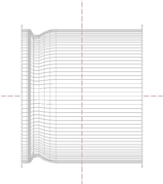
I know it might sound a little crazy, but I’m trying to draw an F1 car on CAD, both as a 3D drawing exercise and as a regulations interpretation exercise. It may take months, years, or I may never complete it, but I’ll try to design a car compling to today’s regulations, and I’m going to post my progress here, and I’ll gladly accept tips and opinions. At this moment I have only drawn the front tyres and the skid block. I’ll try to draw the rear tyres anad the survival cell next week
Front tyre:
Firstly I took the tyre and wheel dimensions from Pirelli’s website and the FIA regulations respectively. Front wheels can be between 305mm and 355mm at the front, so I chose the minimum width, although probably Pirelli has its own specifications regarding that.
http://www.flickr.com/photos/81220033@N04/7443108576/
Here I did cut half of the drawing, since we only need a profile to revolve around an axis to make the wheel. The areas shaded in grey are exclusion zones, were no part of the wheel may be. I haven’t drawn the inner part of the wheel, since it is not a revolution surface
http://www.flickr.com/photos/81220033@N04/7443089988/
Then we view it in a isometric perspective…
http://www.flickr.com/photos/81220033@N04/7443107858/
And revolve it around the axis!
http://www.flickr.com/photos/81220033@N04/7443104722/
Here are some other pictures of the complete wheel:
Tyre, front
http://www.flickr.com/photos/81220033@N04/7443094912/Wheel, front
 25th June 2012, 22:21 at 10:21 pm #204176
Estesark
ParticipantGood work! How long did it take you to do what you’ve posted so far? I imagine the whole project will take an extremely long time. I’d be interested in seeing your progress though, so good luck with it :)
26th June 2012, 1:10 at 1:10 am #204177GuilhermeParticipantAbout an hour and a half or so, but I spent quite a lot of time trying to understand the regulations and getting past some language barriers. I have to do the rear tyres now but I think I’ll be done with them much faster than the fronts. And thank you, I’ll try to keep this updated :)
26th June 2012, 2:18 at 2:18 am #204178F1Yankee
Participantsweet! what software are you using?
26th June 2012, 2:27 at 2:27 am #20417926th June 2012, 5:13 at 5:13 am #204180GuilhermeParticipantI began working on the survival cell. At this moment I have only done the part from the from just after the cockpit open up to the crash structure. It’s obvisouly a little crude because I wanted to do this before going to sleep, but I want to add more detail to the front bulkhead.
Anyway, the minimum dimensions are pretty strictly set by the FIA. the dash and front bulkheads have minimum heights and widths, and since there is not much to gain by making a large or tall cockpit, I guess it’s no wonder the cells look so much alike. Anyway, I’ve chosen the minimum dimensions for the dash bulkhead, but my front bulkhead is 4 centimeters largar than required, because I like larger cockpits :P The spacing between them is 925 milimeters
http://www.flickr.com/photos/81220033@N04/7445698332/
Now, I’m not going the step nose route here. Since I’m not working on the reference plane yet I guess there is no much point in talking about heigths, but my plan is to make the dash at 565mm from the reference plane and the front at 550 (the maximum height of the nose).
http://www.flickr.com/photos/81220033@N04/7445697960/
Yeah, I know, it’s looking like a Ferrari, but red is my favourite colour, nothing I can do about it :P If anyone has some tips as to how to represent carbon fiber better, let me know. I’m having some serious trouble with 3D surfaces with round edges at the moment, so I had to do a pretty shoddy solution there, with two 2D hatches on top of each other, one to give the surface a colour and the other to make that threaded pattern. Anyway, I want to add more detail there, maybe draw those brake fluid containers and such :P
29th June 2012, 4:07 at 4:07 am #204181damonsmedley
ParticipantThis is a brilliantly crazy idea. I absolutely love it. I really hope you continue with this because it will be a lot of fun to see your very own 2012-spec F1 car develop!
29th June 2012, 9:29 at 9:29 am #204182andae23
ParticipantGreat project! I’ve been dreamig about doing this myself, but I’ve never found enough time to do a complete F1 car. Good luck!
29th June 2012, 15:01 at 3:01 pm #204183Joey-Poey
ParticipantI think this is actually a very cool (if ambitious) exercise! Will probably give you a new perspective on what the teams go through to pump these cars out every year. Please continue to keep us updated because I’m really interested in hearing what sort of problems you come across and your own solutions. It’d be neat to see what the average Joe off the street is able to do with the same regulations the professionals deal with.
29th June 2012, 17:24 at 5:24 pm #204184joac21
Participantill try to find the equivalent command of Sweep to rail (wich is used in other 3d software) for autocad..
29th June 2012, 17:48 at 5:48 pm #204185 the_sigmanParticipant
@guilherme Fantastic idea, well done and good luck
29th June 2012, 18:39 at 6:39 pm #204186 Keith CollantineKeymaster
Cool project @guilherme – good luck with it!
29th June 2012, 19:09 at 7:09 pm #204187John Ward
ParticipantVery interesting project, not crazy at all, would like to follow your progress, good luck and all the best.
29th June 2012, 21:26 at 9:26 pm #204188matt90
ParticipantGood luck, I look forward to seeing how you get on!
29th June 2012, 23:27 at 11:27 pm #204189 Lin1876Participant
This is really epic.
Out of interest, have you any plans for your finished model? Given your understanding of the car, you could potentially add it into a game or something like that.
- AuthorPosts
- You must be logged in to reply to this topic.